Find all relevant information to use DaSCR-Machine here!
This the multi-page printable view of this section. Click here to print.
DaSCR-Machine
- 1: Overview
- 2: Hardware
- 2.1: Electronics
- 2.2: Tools
- 2.3: Case
- 3: Overall Cost
- 4: Pinout
- 5: Build the case
- 5.1: Step 1 - Segment section
- 5.2: Step 2 - Matrix Section
- 5.3: Step 3 - Back panel and unit alignment
- 5.4: Step 4 - The door
- 5.5: Step 5 - Side panels
- 5.6: Step 6 - Painting the case
- 5.7: Step 7 - Segments and piezo sensors
- 5.8: Step 8 - Fitting electronics
- 5.9: Step 9 - Cable management
- 5.10: Step 10 - Door with lock
- 5.11: Step 11 - LED strip
- 5.12: Step 12 - Applying numbers
- 5.13: Step 13 - Finish PCB
- 6: Arduino
- 7: Raspberry Pi
- 8: Custom designed PCB
1 - Overview
Get started with DaSCR-Machine, your very own softdart machine
You ready for some soft dart goodness?
What is it?
DaSCR-Machine is an Arduino based soft dart machine sending your score to DaSCR-Board as a score tracking app. The software components are written in C++ on the Arduino side and the service communicating with the scoreboard is written in go.
Why do I want it?
You are tired of cheap soft dart boards breaking after a few weaks intensive game play? You want a machine like a “Löwen Dart HB8” but not wanna pay 1500 bugs for it? So this one might be for you.
-
What is it good for?: DaSCR-Machine is a cool project to work on in your spare time. It will give you a fully fledged darts machine in high quality when succeeding.
-
What is it not good for?: I did not and will not add display, segment display or such to this software. As it is open source you are very welcome to implement it yourself.
Where should I go next?
- Hardware: Get started with DaSCR-Machine
2 - Hardware
You need to know what hardware you are supposed to have - so look in here!
I will split this section in what I bought to build this bad boy and what I already had by hand. You will need to apply this to your situation as you might not have everything layin around readily available, though.
Notice
As I am from Germany if I refer to a price it will be in Euro (€) and all the links will lead to German shops. Also the distance measurements are in metric system (mm).2.1 - Electronics
Everything you will need which has to do with electronics
This is what I bought to build the machine:
- Arduino Mega 2560 (cheaper Chinese clone): Amazon DE
- Raspberry PI 4: Amazon DE
- Arcade Button with LED: Amazon DE
- Piezo Knock Sensors: Amazon DE
- Ultrasonic Sensor (HC-SR04): Amazon DE
- Löwen complete set with matrix: DartDoktor.de
- Casing Lock: DartDoktor.de
2.2 - Tools
A basic overview of tools and little parts I used to build the machine
This tools and parts I had laying around:
- Solder Iron
- Cables
- Prototyping Breadboard
- Perforate board
- Resistor set
- Shrink tube
- LED strip 12V
2.3 - Case
Everything you need to buy to build the case itself
I was following this Youtube Video to design my case and therefore bought:
MDF (medium-density fiberboard)
- For the segments: 480mm X 520mm X 12mm
Plywood
- matrix: 520mm x 520mm x 18mm
- door: 600mm x 750mm x 12mm
- back panel: 600mm x 750mm x 12mm
- 3 times front board: 750mm x 200mm x 12mm
- bottom: 750mm x 200mm x 12mm
3 - Overall Cost
Calculation of the overall cost
As I was asked a lot lately here are the overall costs
- Arduino: 16,00 €
- PCB: 7,50 €
- Raspberry Pi: 58,00 €
- SD Card: 7,00 €
- Button: 8,00 €
- Piezos: 10,00 €
- Ultrasonic Sensor: 4,00 €
- Löwen set with matrix: 190,00 €
- Case Lock: 10,00 €
- MDF: 2,50 €
- Plywood: 45,00 €
- Color: 9,00 €
- Inking roller: 4,50 €
- Self-adhesive numbers: 20,00 €
Not taken into account
- LED strip: about 15,50 €
- Power supply: 20,00 €
- Little parts like wires, resistors, shrink tube, …: 25,00 €
Overall
The cost of this machine is about: 452 € total.
Notice
Please be advised that prices for the components might change. This calculation was valid for when I built the machine.4 - Pinout
This is the pinout used with the Arduino Mega 2560
To ease the pain of wiring this all to the arduino I created a pcb to function as a header on the Arduino Mega 2560. You can find it in the Github Repo and can order it online for example here.
| Component | PIN | Arduino PIN |
|---|---|---|
| Push Button | LED + | 3 |
| LED - | GND | |
| Signal + | 2 | |
| Signal - | GND | |
| Ultrasonic Sensor | VCC | 5V |
| TRIG | 9 | |
| ECHO | 8 | |
| GND | GND | |
| Piezo 1 | S | A0 |
| - | GND | |
| Piezo 2 | S | A1 |
| - | GND | |
| Matrix socket | 1 | 22 |
| 2 | 24 | |
| 3 | 26 | |
| 4 | 28 | |
| 5 | 30 | |
| 6 | 32 | |
| 7 | 34 | |
| 8 | 36 | |
| 9 | 38 | |
| 10 | 40 | |
| 11 | 42 | |
| 12 | 44 | |
| 13 | 46 | |
| 14 | 48 | |
| 15 | 50 | |
| 16 | 52 | |
| 17 | 53 | |
| 18 | 51 | |
| 19 | 49 | |
| 20 | 47 |
5 - Build the case
Now you need to use your tools
This instructions will be devided into different steps.
Use the menu to go throught the process of building the case.
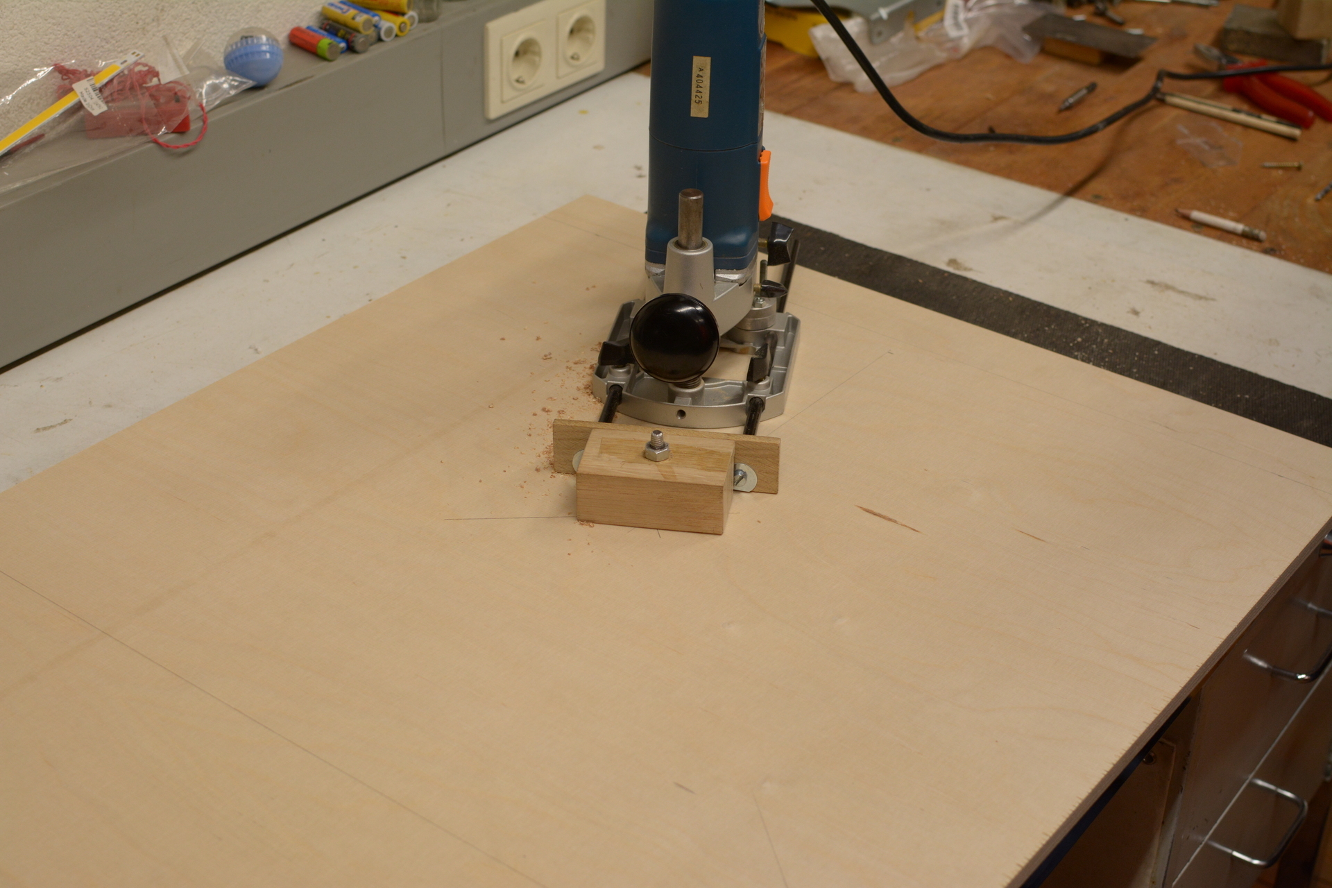
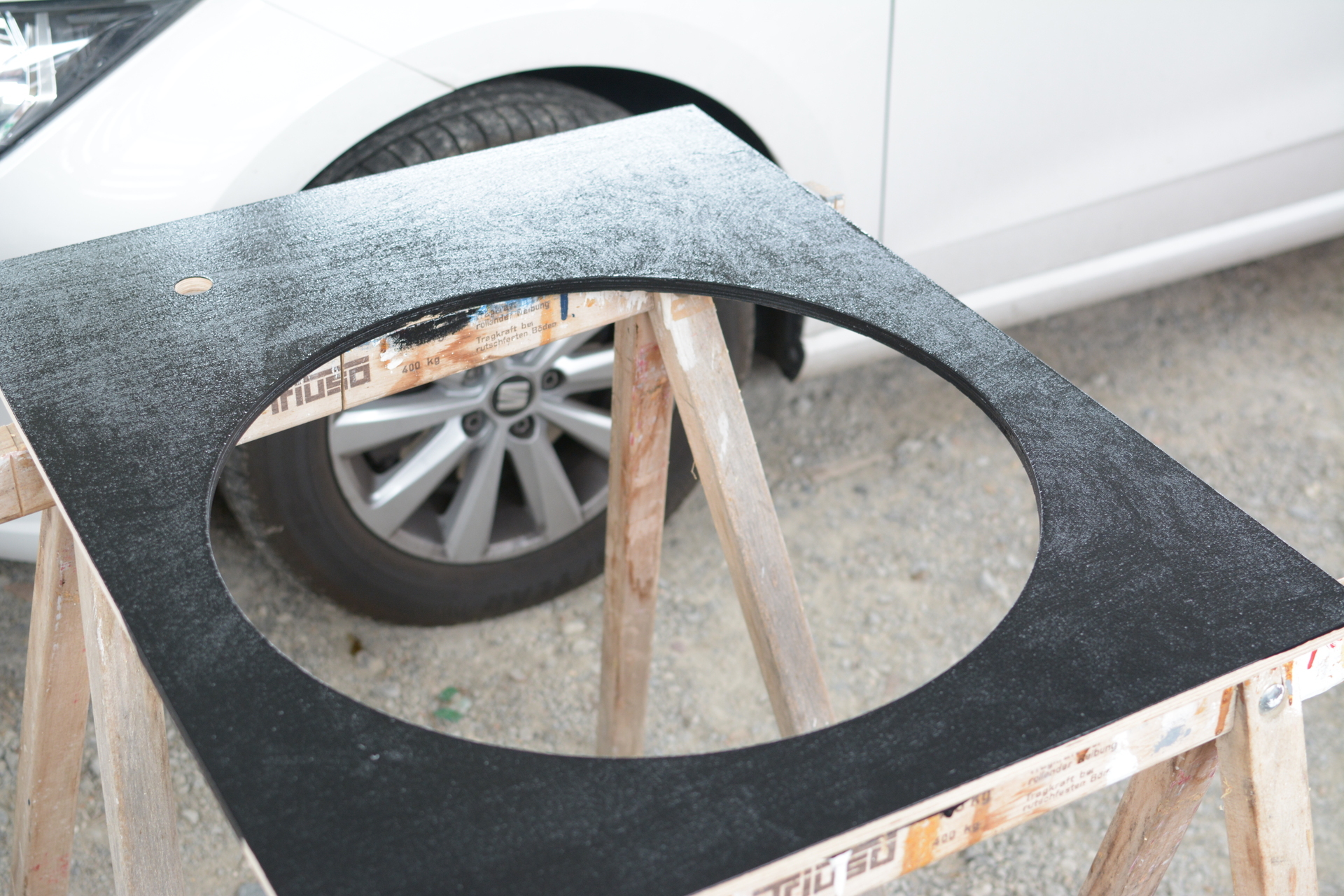
5.1 - Step 1 - Segment section
Build the segment section with spider
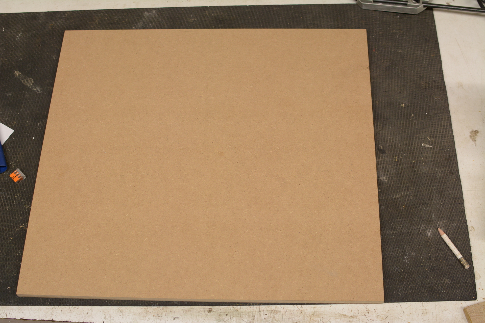
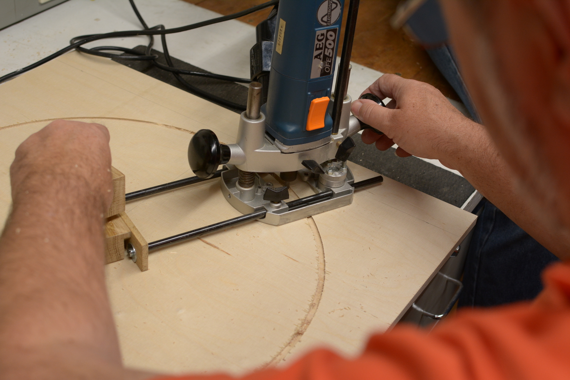
The segment section is made of MDF and is 480mm X 520mm x 12mm.
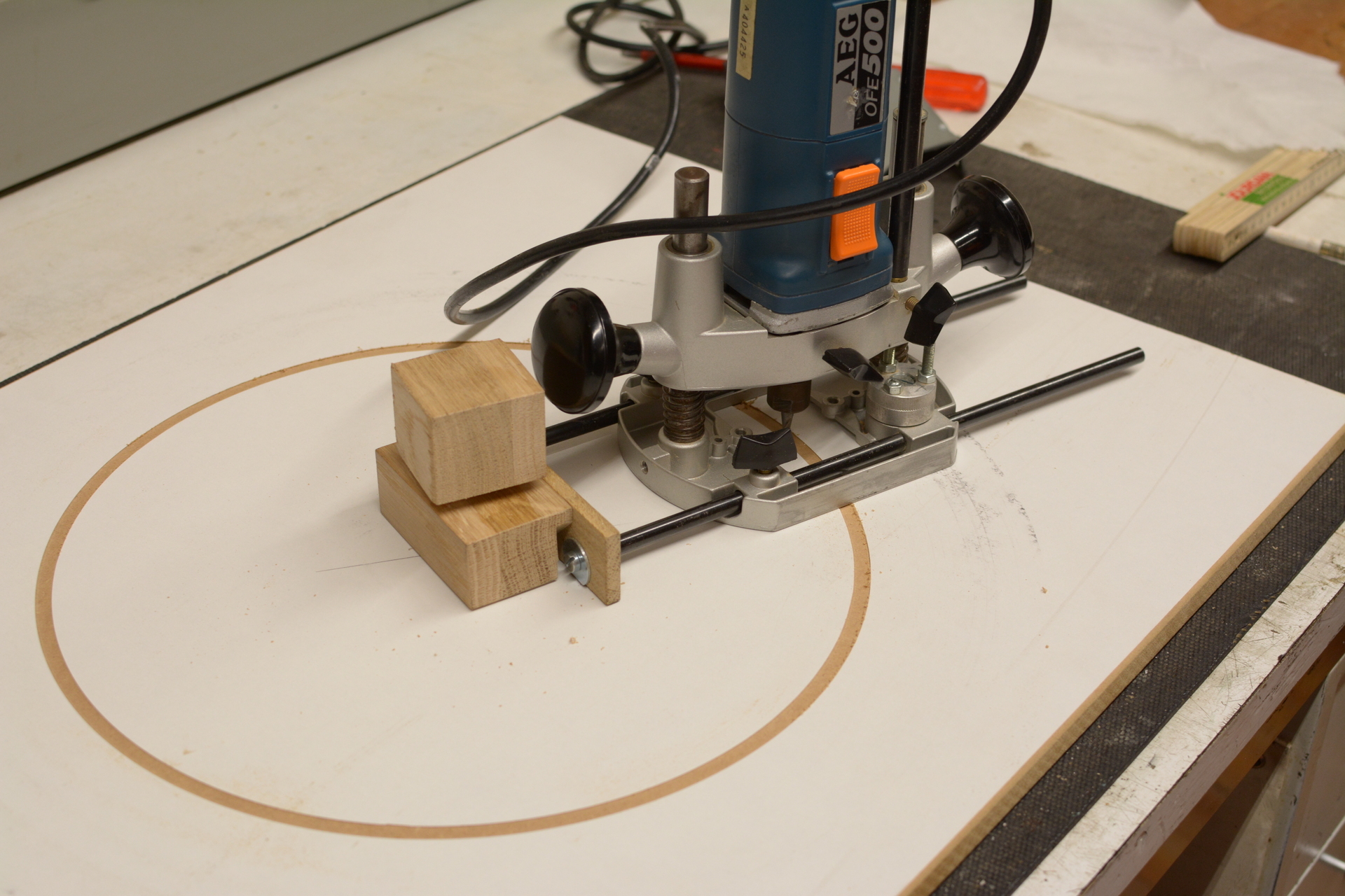
First you define the center of the board for the router to be locked in place. Then you might want to test your jig to see if you are able to cut a perfect circle. We did so with a leftover wood piece.
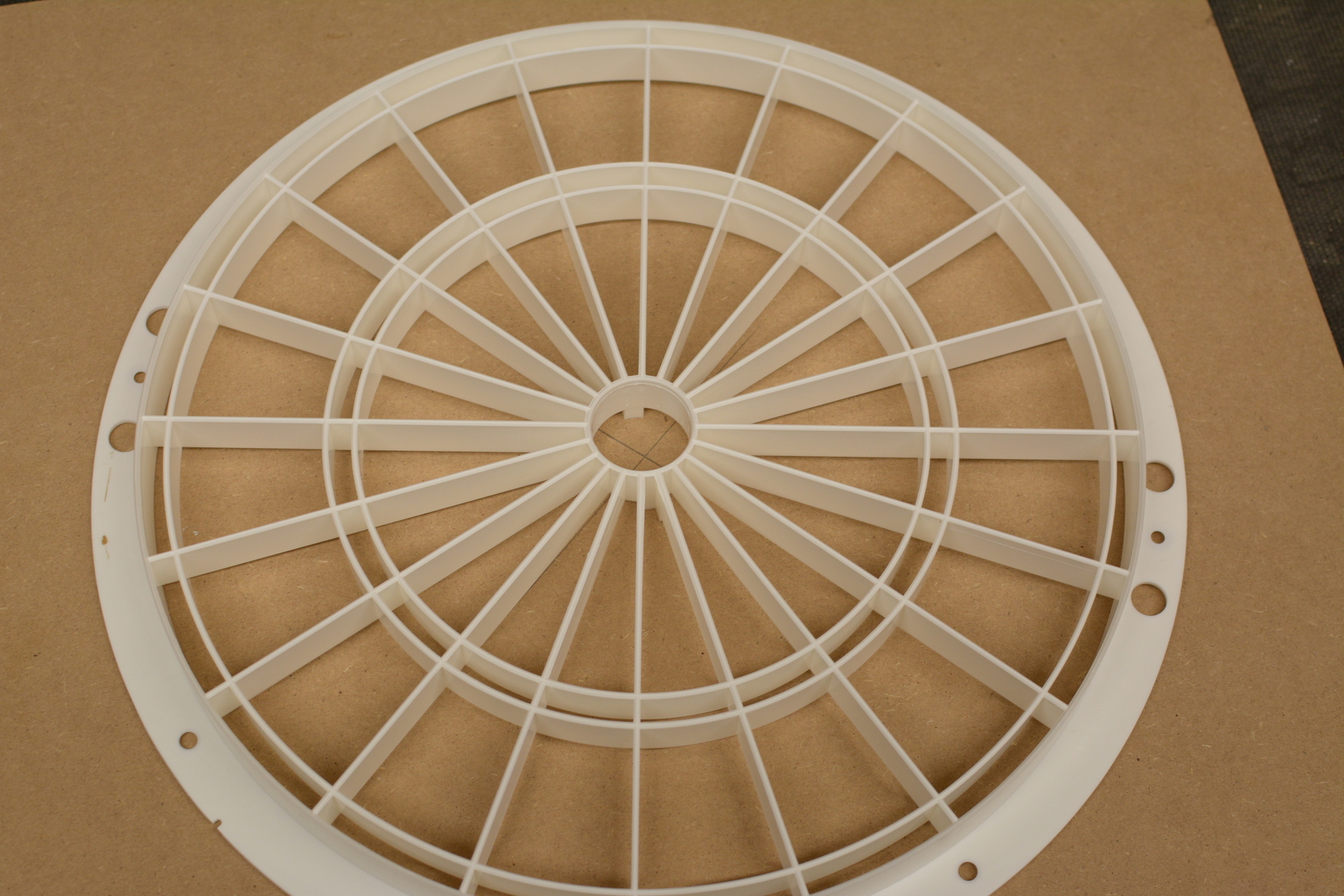
So now for the fun part. First you take of 2 mm of the outer radius of the spider for it to be even to the board later on. Then you cut through the board with the inner radius for the spider to be able to stick through the board later on.
We did so by doing the cut from one side until half the thickness of the board. Then we flipped over the board and did the final cut from the other side. This way you will prevent from having splinters all over the place.
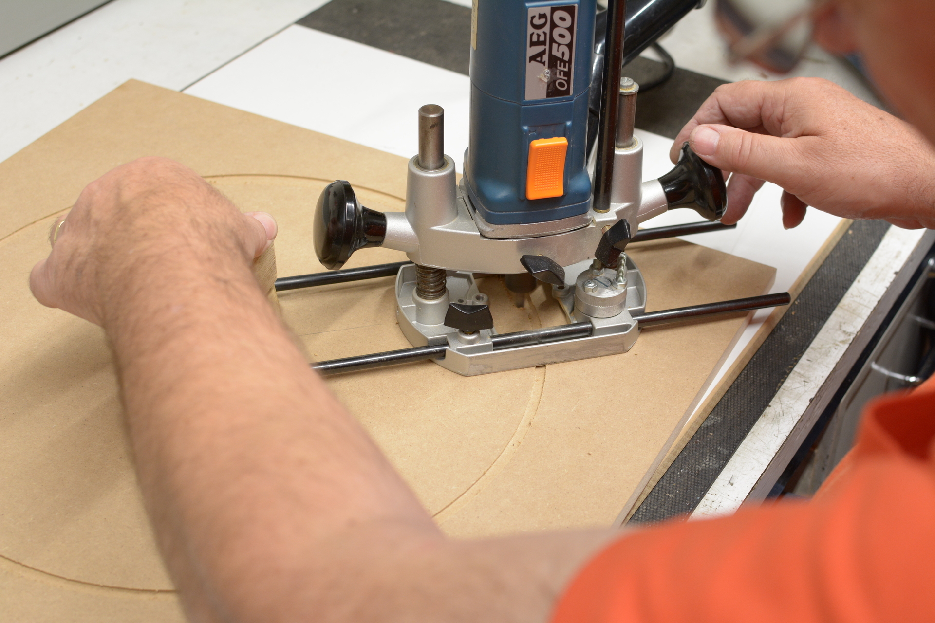
Now you can fit the spider through the hole and screw it to the board. Be sure to align it properly first. At the back side of the board it is supposed to be plane even so it can be fitted to the matrix section later on.
Finally you can now screw the catch ring segments to the front side of the segement section by screwing them in place from the back side of the board.
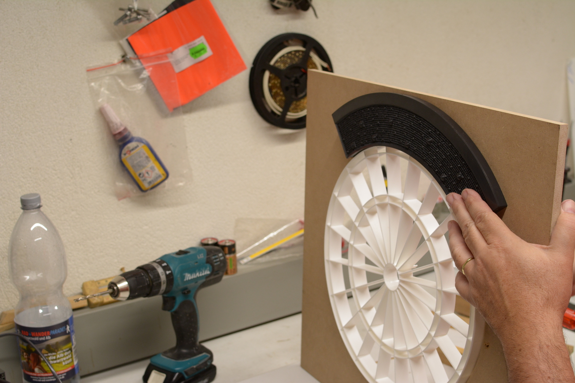
The segment section with spider is now finished. Continue with building the matrix section.
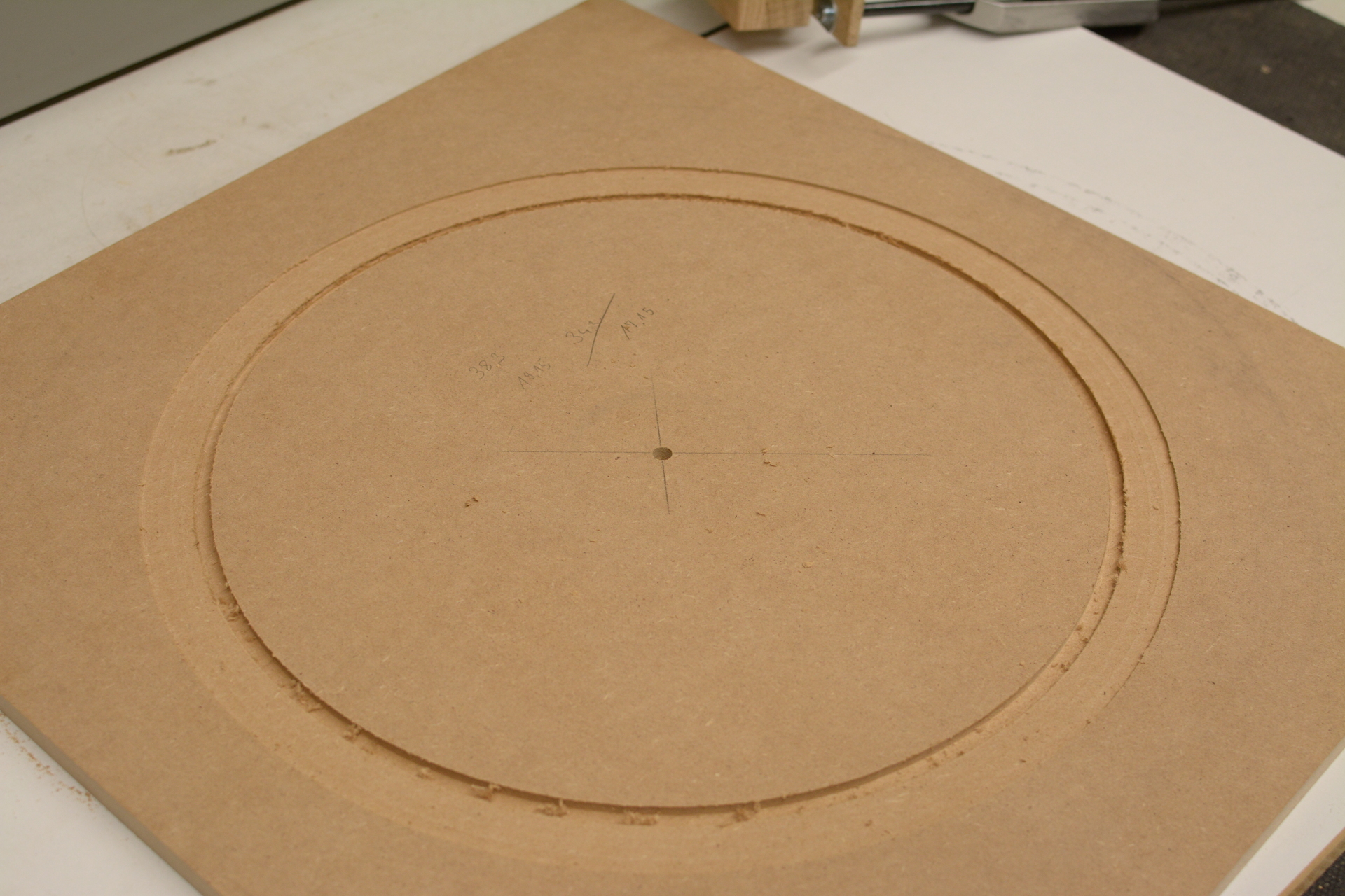
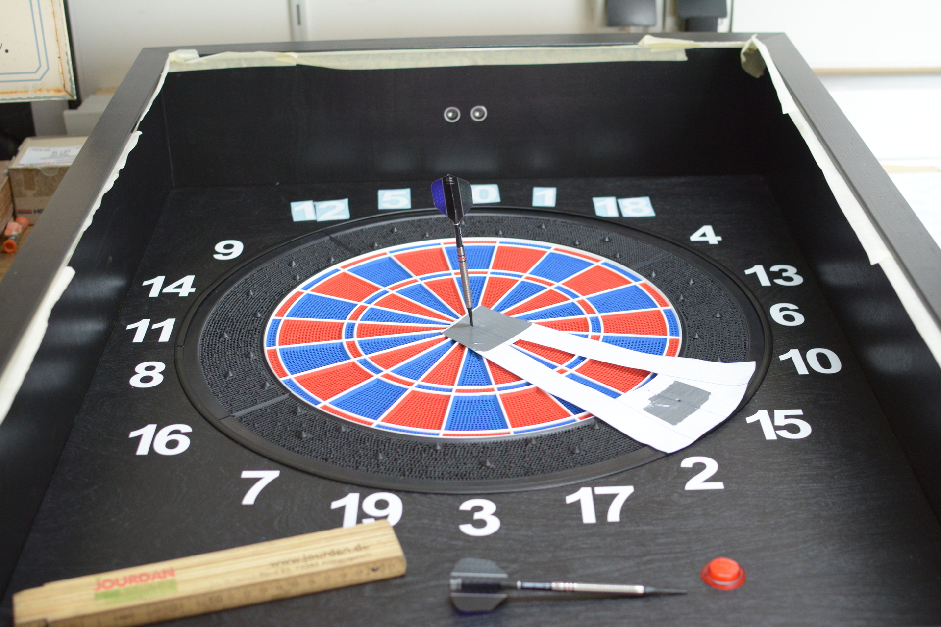
5.2 - Step 2 - Matrix Section
Build the matrix section
The matrix section is made of plywood and is 520mm X 520mm x 18mm.
You need to measure the exact middle of the board and then you draw a cross like in the picture. Although the matrix has a paper on its sticky side you should be able to see through an perfectly align the matrix. Also for orientation you might want to use the pressure points of the matrix.
Attention!
It is crucial for the machine to work as desired that the matrix is perfectly aligned. I cannot stress this enough!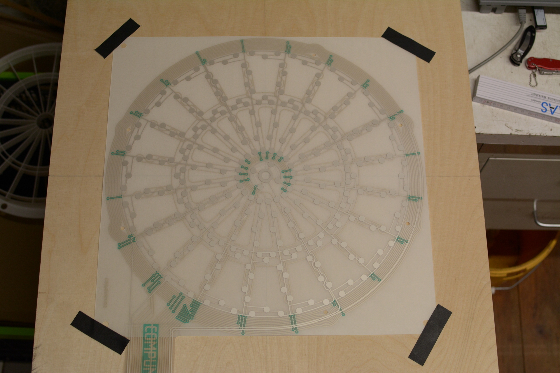
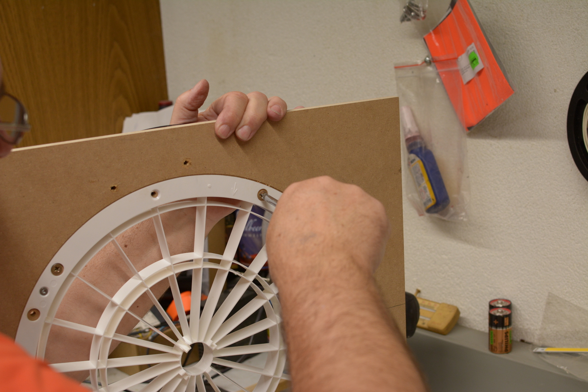
At this point you do not yet stick the matrix to the board using its sticky back. You better fit the segment section to the matrix section now and test the function.
If that is the case you mark the position of the matrix with a sharpie or pencil on the board, then remove the protective paper from the sticky side of the matrix and then apply it to the board in the marked position. Again, be aware of the marked position and perfectly align the matrix again.
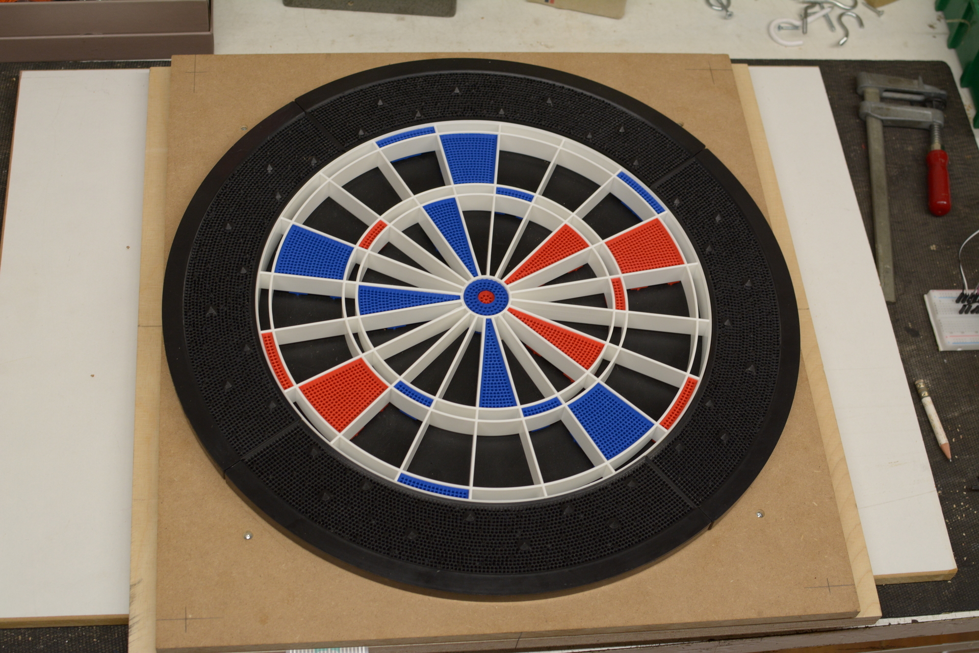
Finally you can screw the segment section to the matrix section. Be sure not to screw through any traces of the matrix below.
The unit is now finished. Continue with aligning the unit on the back panel.
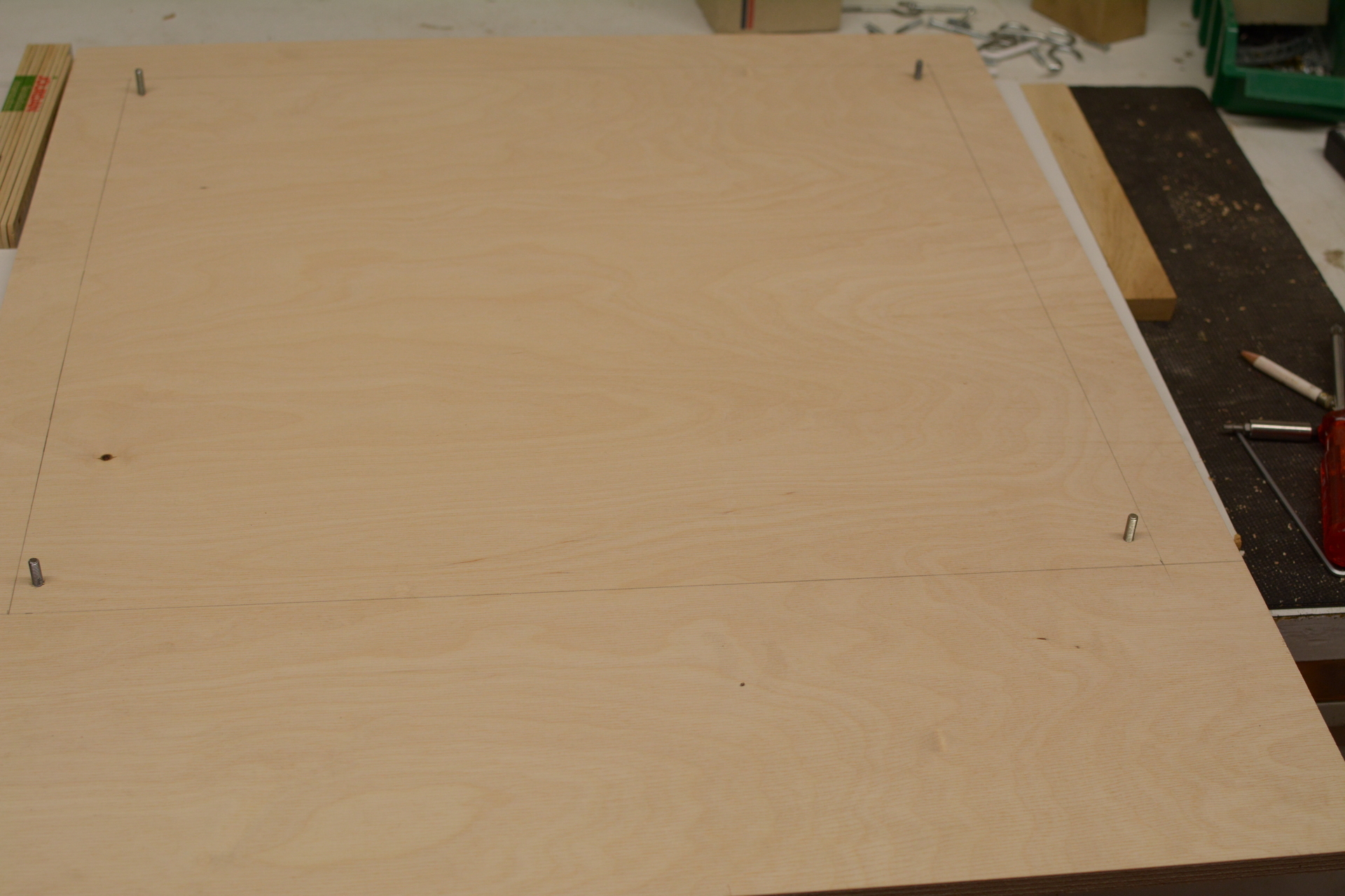
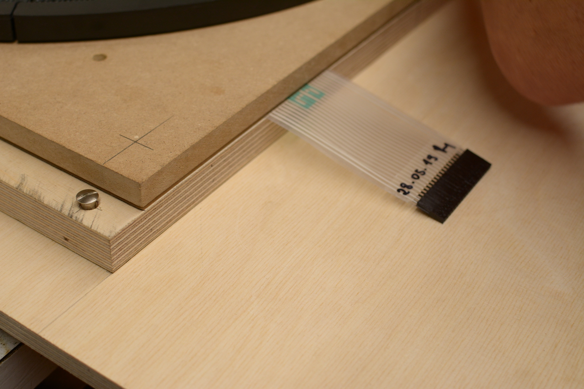
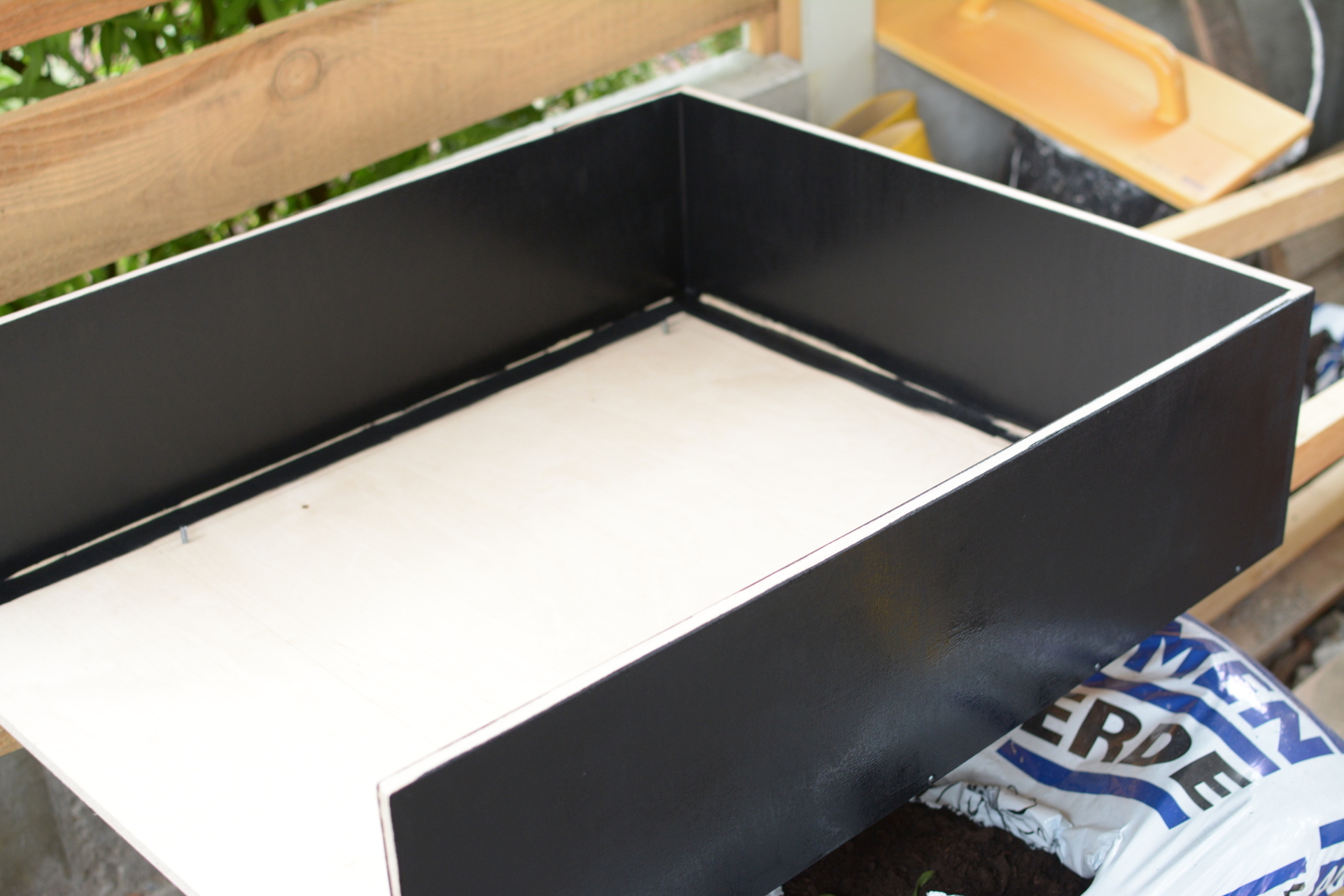
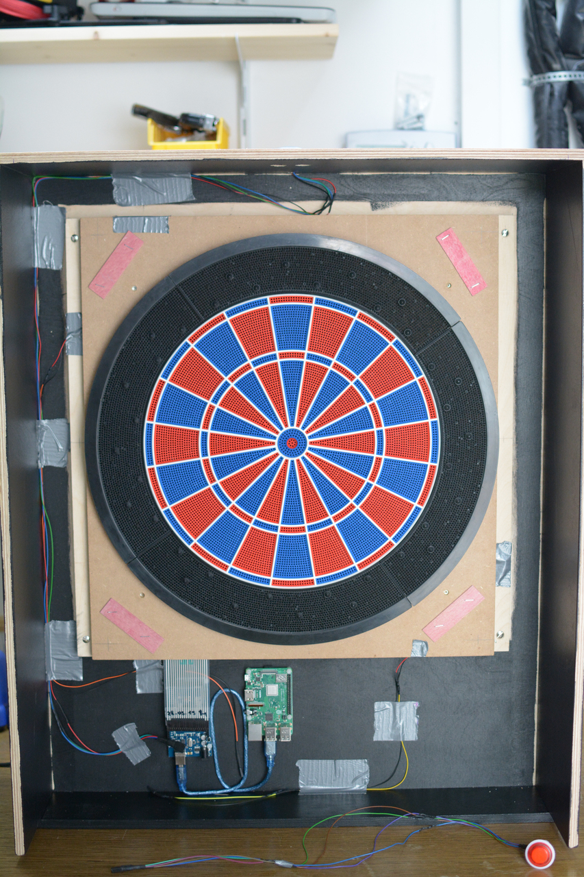
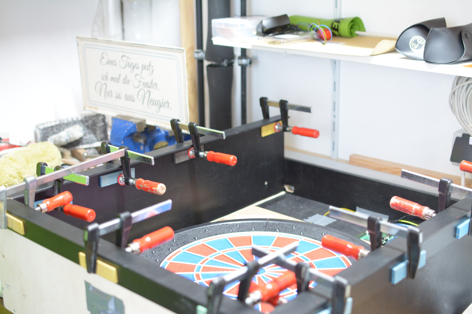
5.3 - Step 3 - Back panel and unit alignment
Build the back panel and align the unit on it
The back panel is made of plywood and is 750mm X 600mm x 12mm.
You now need to align the unit on the back panel. Leave enough space at the bottom to fit the electronics and also be sure to center align it horizontally.
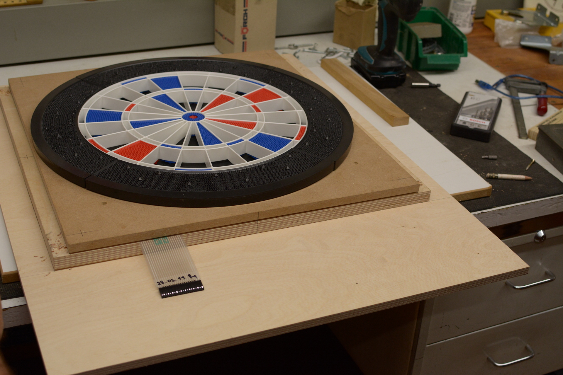
Then you drill through the matrix board and the back panel in every of the 4 corners. I just glued in threaded screws to the back side of the back panel to be able to fixate the unit from the top side of it.

This step is now finished. Next up: the door.
5.4 - Step 4 - The door
Build the door
The door is made of plywood and is 750mm X 600mm x 12mm.
You need to measure and project the exact middle of the dart board (segment section) to the door to be able to cut out the hole for the dart board using your router and the jig.
Now you can cut a hole with the radius of the dart board into the door. Be sure to make it about 1,5 mm bigger as the radius of the board to be able to apply the edge protector later on.
Now you can test the fitting of the door.

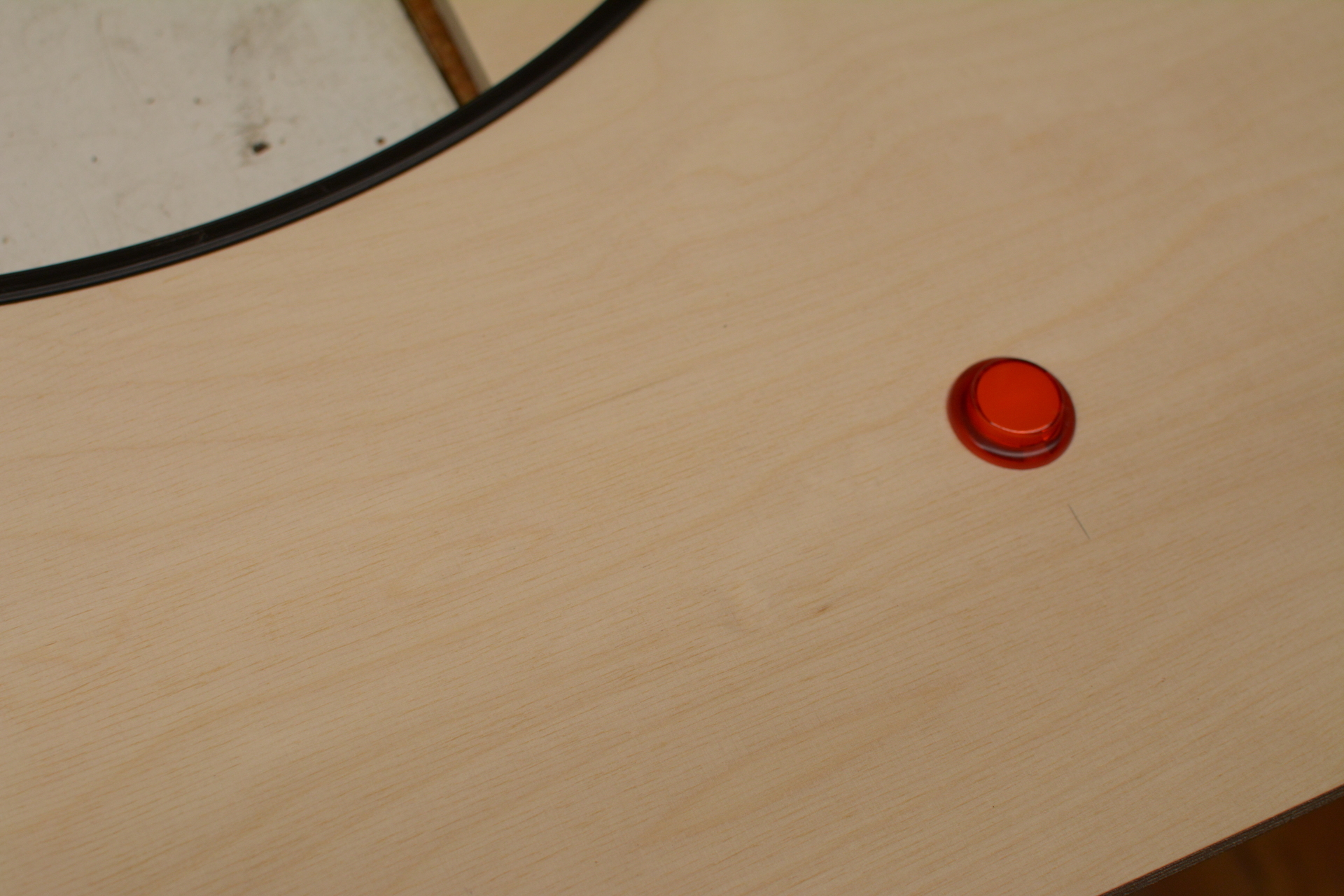
Finally you drill the hole for the button.
The door is now finished. You can continue by applying the side panels then.
5.5 - Step 5 - Side panels
Build the side panels
The side panels are made of plywood and are 750mm X 200mm x 12mm each.
We fitted the side panels onto the back panel from behind. We started by doing the side ones and then fitted another one on the top.
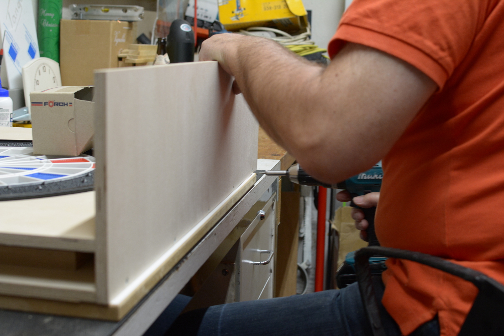
Repeat for all side panels (left, right, top) and then continue with painting the case.
5.6 - Step 6 - Painting the case
I see a red door, and I want it painted black sings…
Next I painted all the parts black. I used a mat black paint. I applied it using a roller. I also just applied it once as the wood pattern was still shining through what I find to look very sexy. If you want that not to happen you might have to paint it a second time.
While the painting dries you can continue by finishing the unit by adding the rest of the segments.
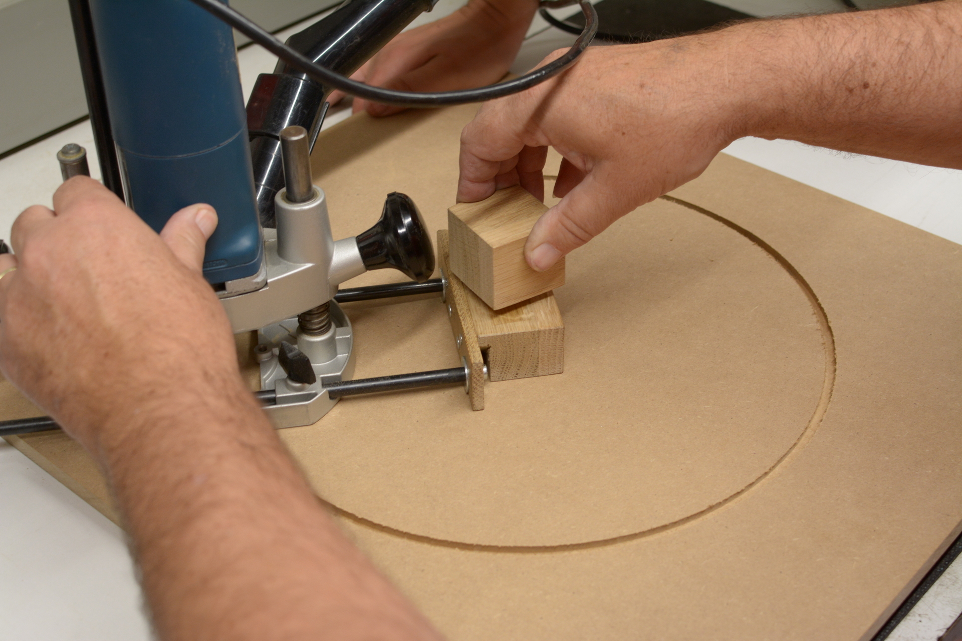
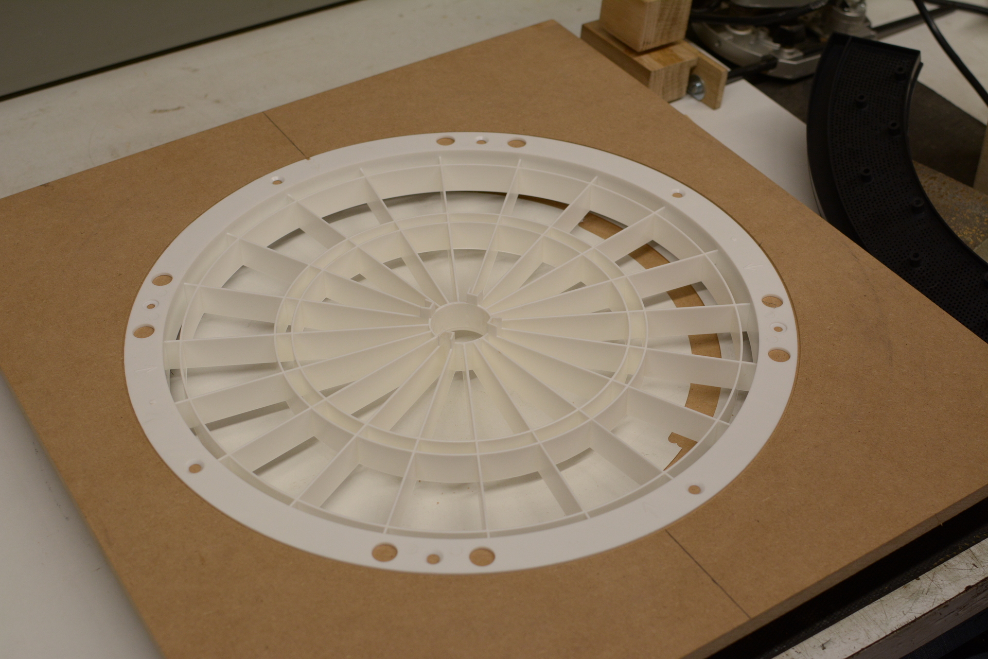
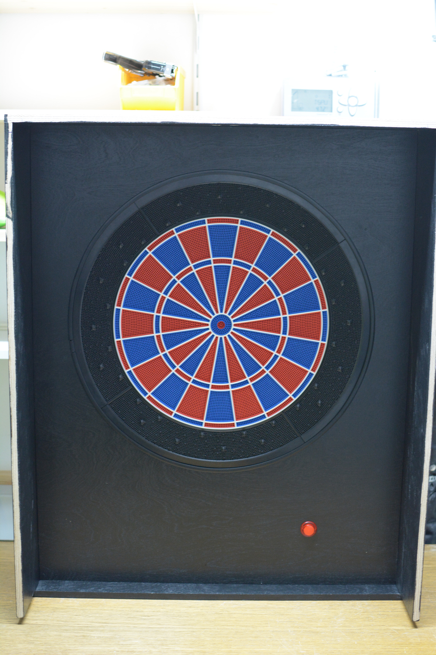
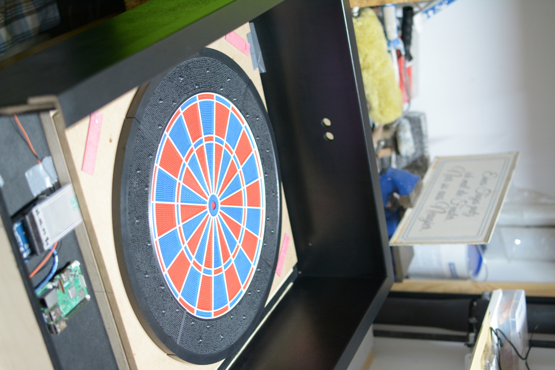
5.7 - Step 7 - Segments and piezo sensors
Finish the unit by adding rest of segments and the piezo sensors
While the color on the case dries you can add the rest of the segments to the segment section.

You will need to separate the segemnt section from the matrix section to do that. So while you are already in you can as well just stick the piezo sensors with a bit of sticky tape to the segment section and let the electronics hang from the side like pictured below.
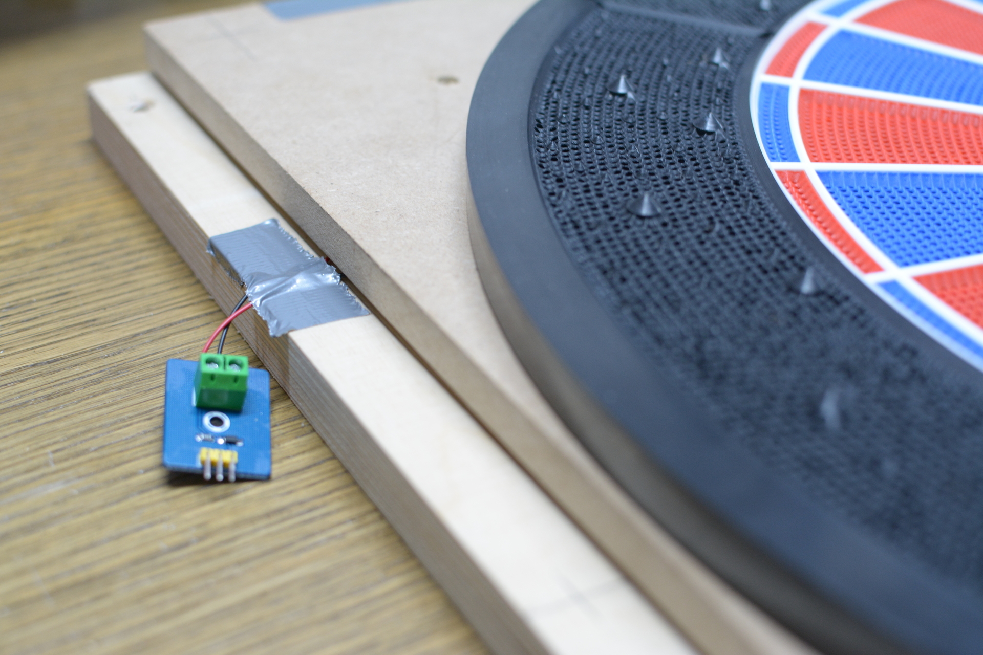
Case is dry now? Well then you can fit the electronics in place.
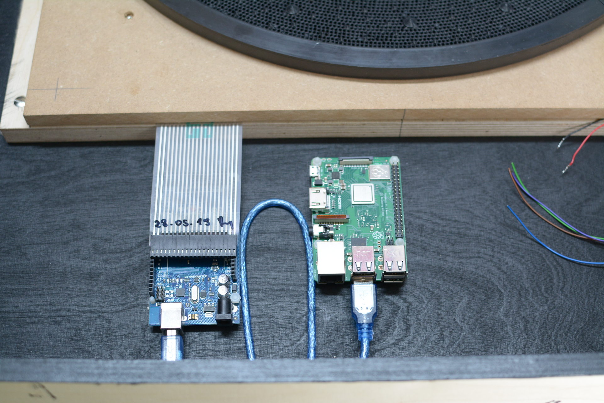
5.8 - Step 8 - Fitting electronics
Install the electronics
I decided to use jumper cables from a prototyping set and just apply shrink tube to the ends for it to look like a plug. So later on it can just be plugged into my custom designed PCB.
Attention!
I used female connectors as I will use my PCB later on which is totally optional. If you want to directly connect your sensors to the Arduino you will need male connectors.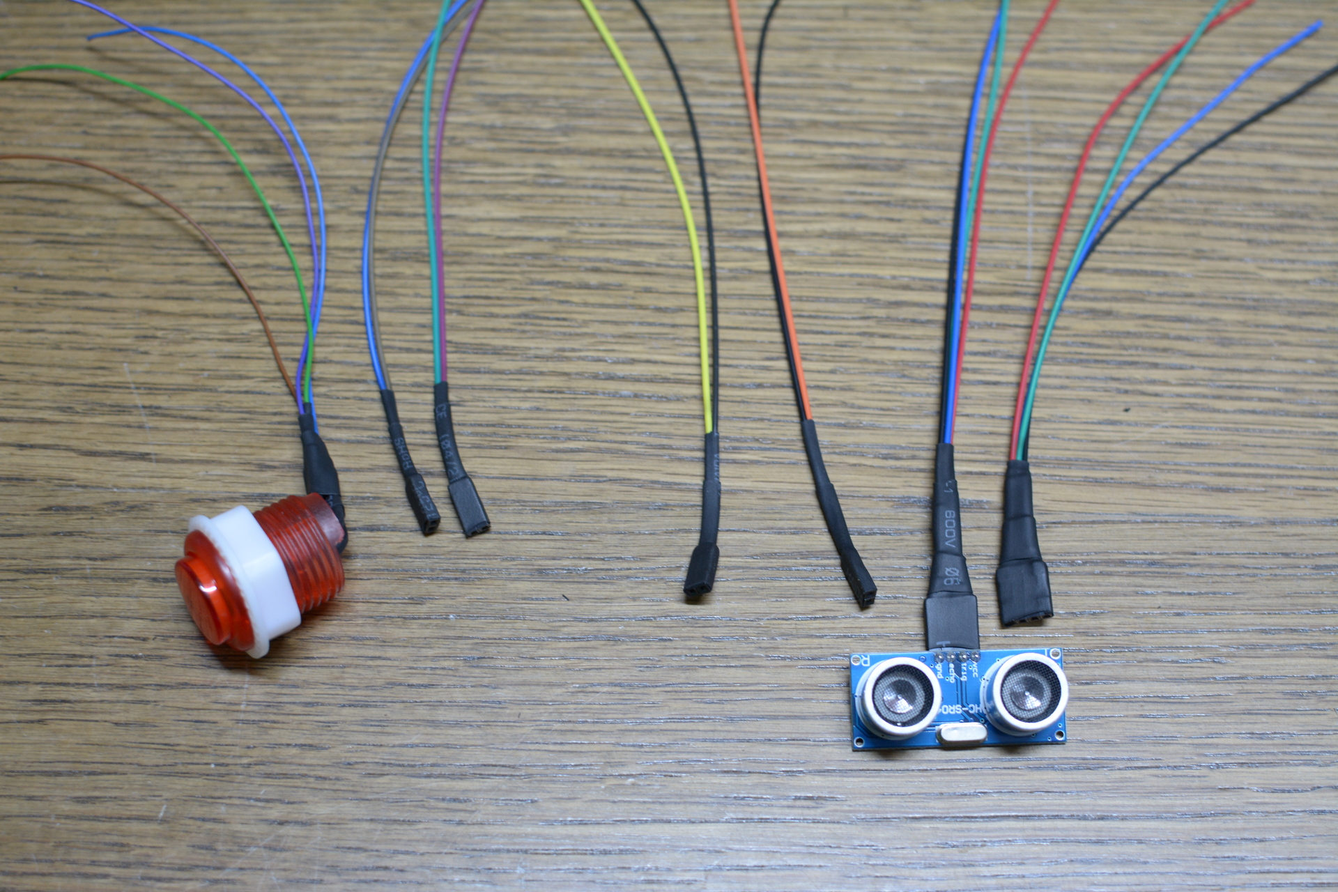
You need to mark the holes for the Arduino and the Raspberry Pi on the right spots, then drill a hole and fixate them. I used plastic standoffs for this job.
Finally you screw the unit back into place.
It’s now time to manage all the cables.
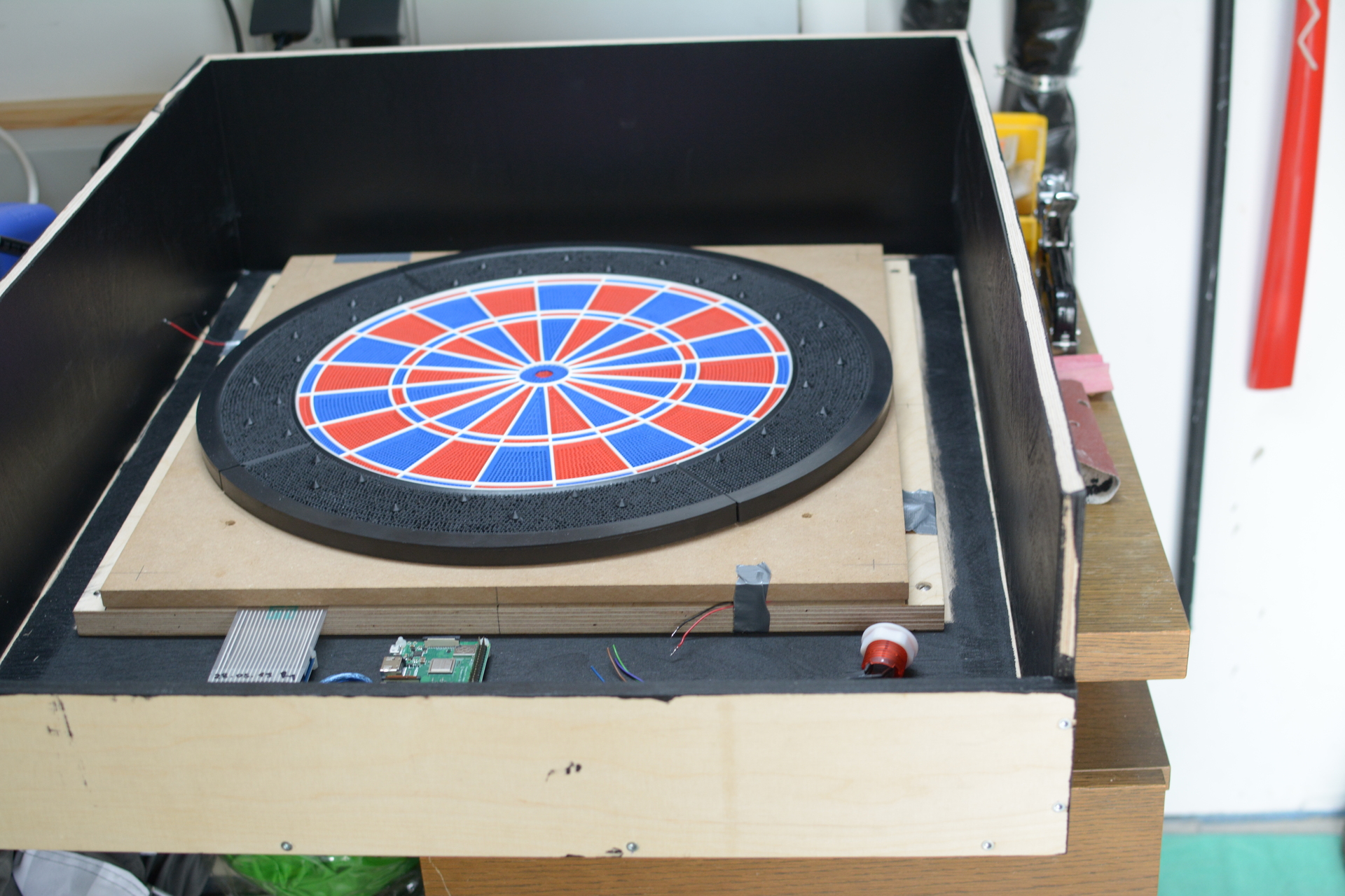
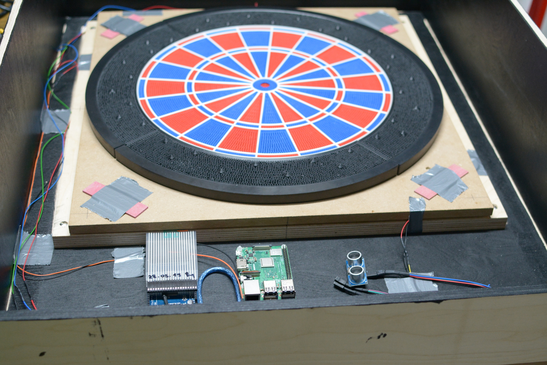
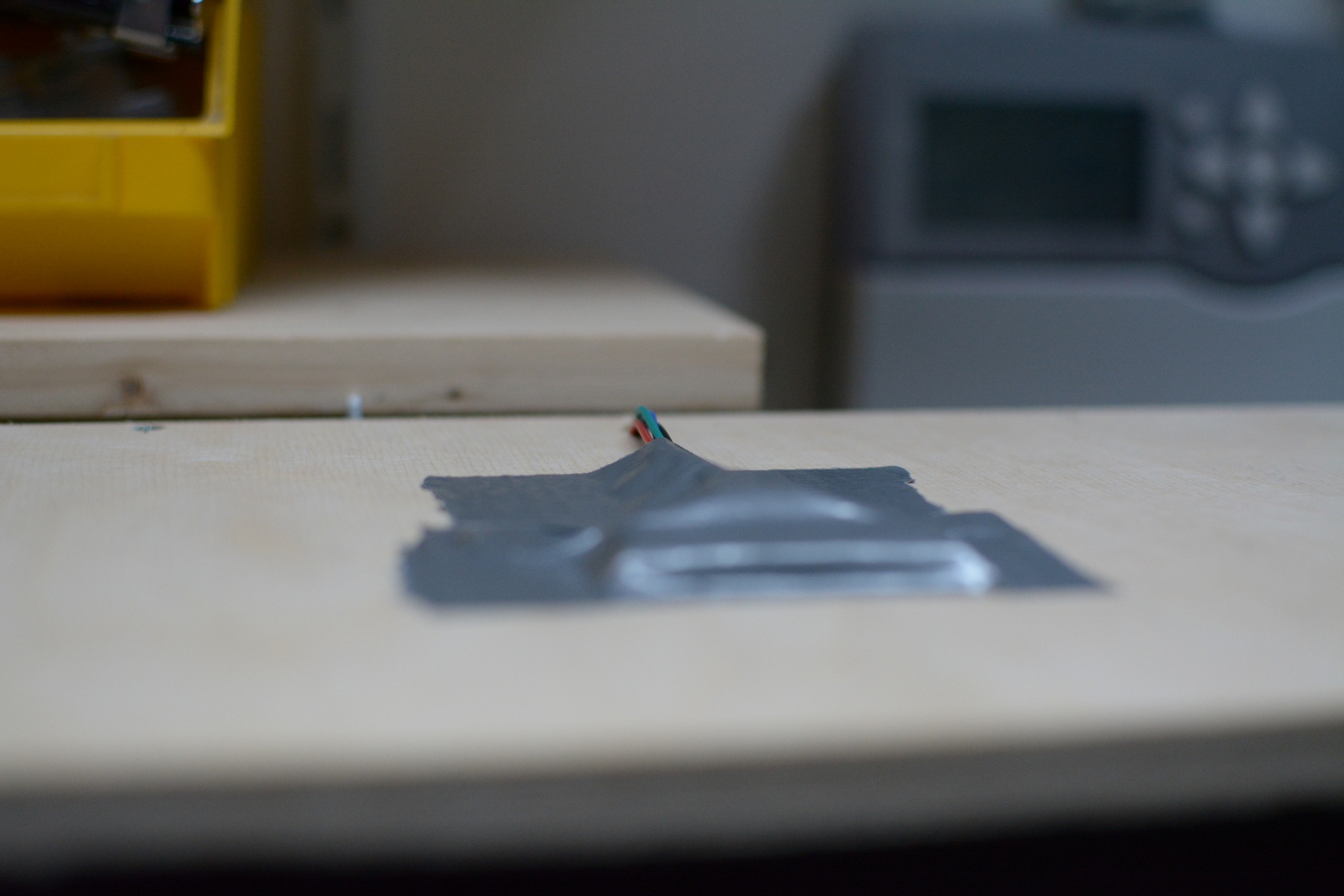
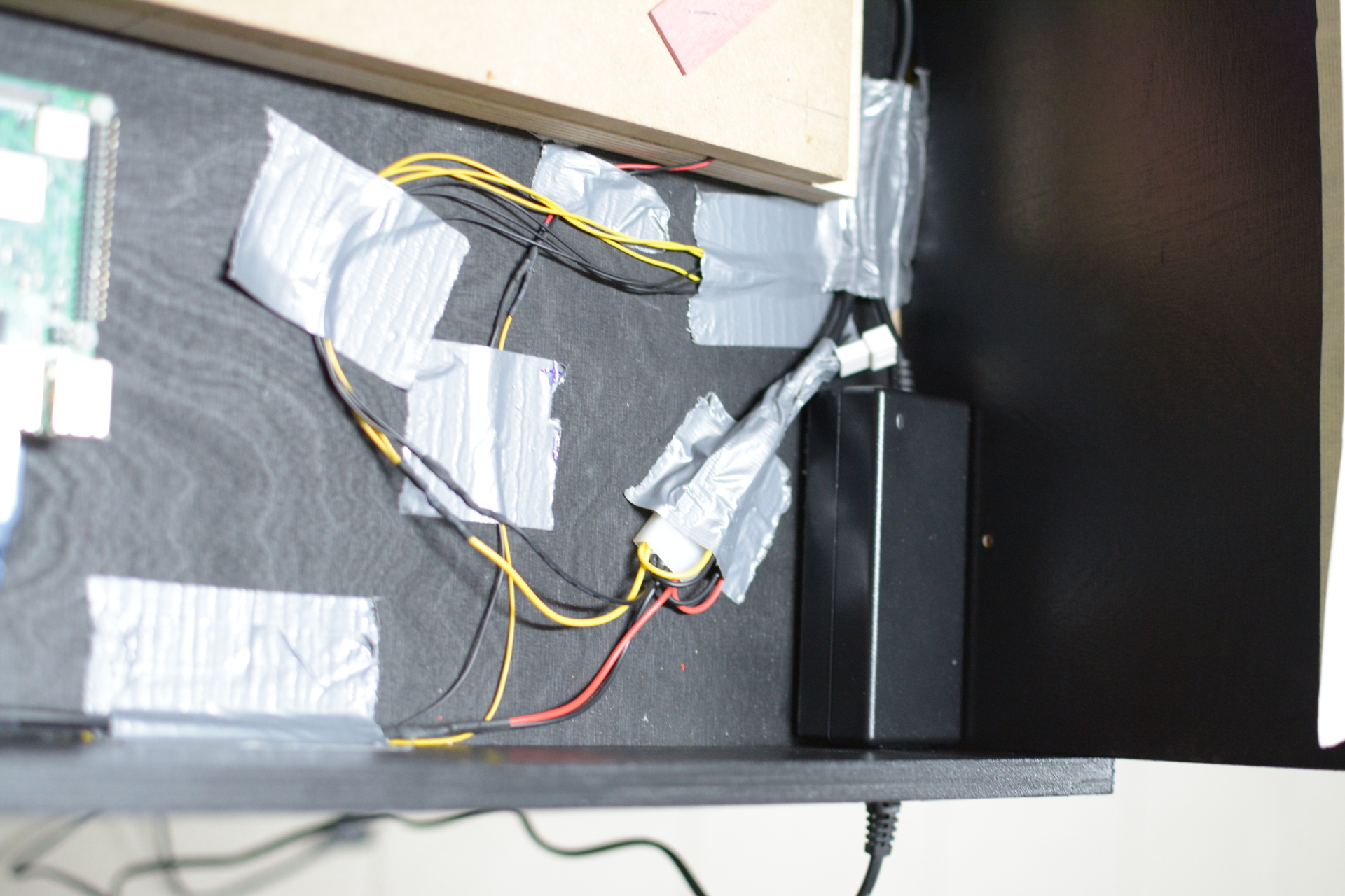
5.9 - Step 9 - Cable management
Run all the cables through the cabinet
Now you can run all the cables through the machine.
I installed the ultrasonic sensor from above drilling two holes in the top plate and ran the cables from behind into the machine and down to the Arduino.
I fixated the cables with duct type here and there. There might be better ways to manage the cables though. After about 2 years now the duct tape starts to come loose. You might want to better apply other, cleaner cable management techniques.

It is now the time to lock the door of the machine.
5.10 - Step 10 - Door with lock
Lock the door!
Now you can fixate the edge protection with a stapler to the hole where the segments go through like in the picture below.
To better lock the door in place I drilled a little hole from the sides and from above through the side panels right into the door. So you can insert a nail as lock machism #1, as you can see from this picture.
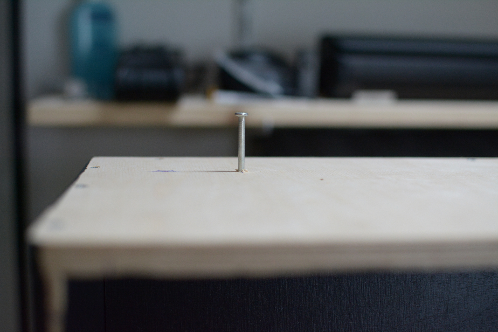
Finally you place the actual lock into the doors bottom edge for example. Be sure to apply a piece of wood to the casing where the lock can lock into place. I sure bet you can figure this without a picture :D

Let there be light!
5.11 - Step 11 - LED strip
And we said, Let there be light: and there was light.
For the light cover I used angular wood, painted it and glued it to the front of the casing as you can see from the picture below.
Now there is enough room to stick the LED strip onto the covers bottom side. To prepare for this I cut the strips to size and soldered the cables for the power to them already.
The strip has a sticky side itself which I applied to the bottom side of the covers. I also secured them temporarily with additional sticky tape.
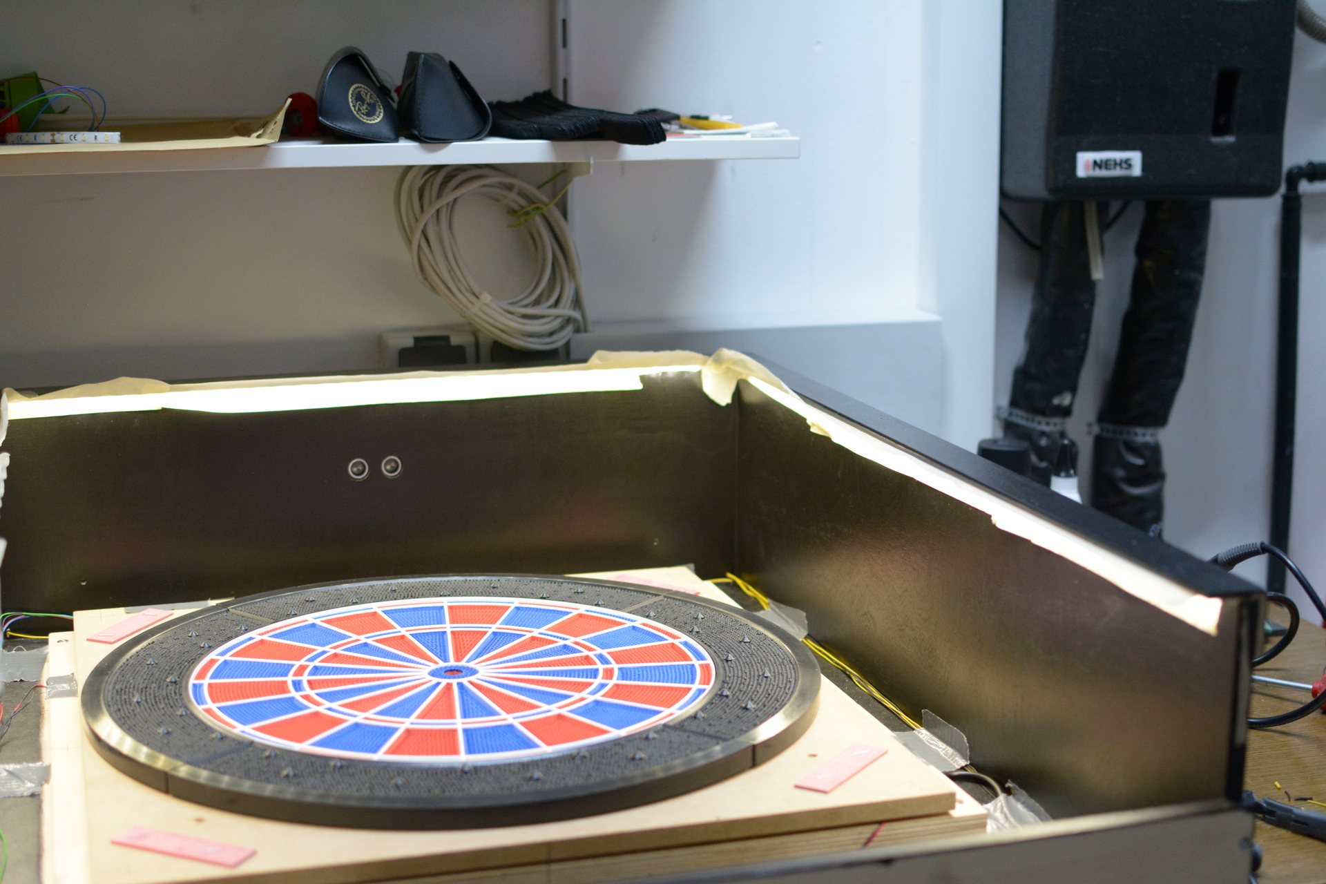
The black and yellow cables on the side of the case are the LEDs power cables. I ran them at the top outside the machine like I did with the ultrasonic sensor and drilled them back into the case at the bottom level so no one will see any cables while playing.
The power supply has one 12V, 5A side where I connected the LED strips to. The are not controlled by the Pi or the Arduino, but will just light up as the machine gets power. You might as well want to run them through one of the systems to be able to control when they light up. Then you could let them blink and such. I decided not to.
I drilled a hole into the bottom bit of the machine to be able to run a connecting cable into the the power supply, as well as a network cable.
The black and red cables are connected to the Raspberry Pi and will deliver power to it.
You need to count on the next one!
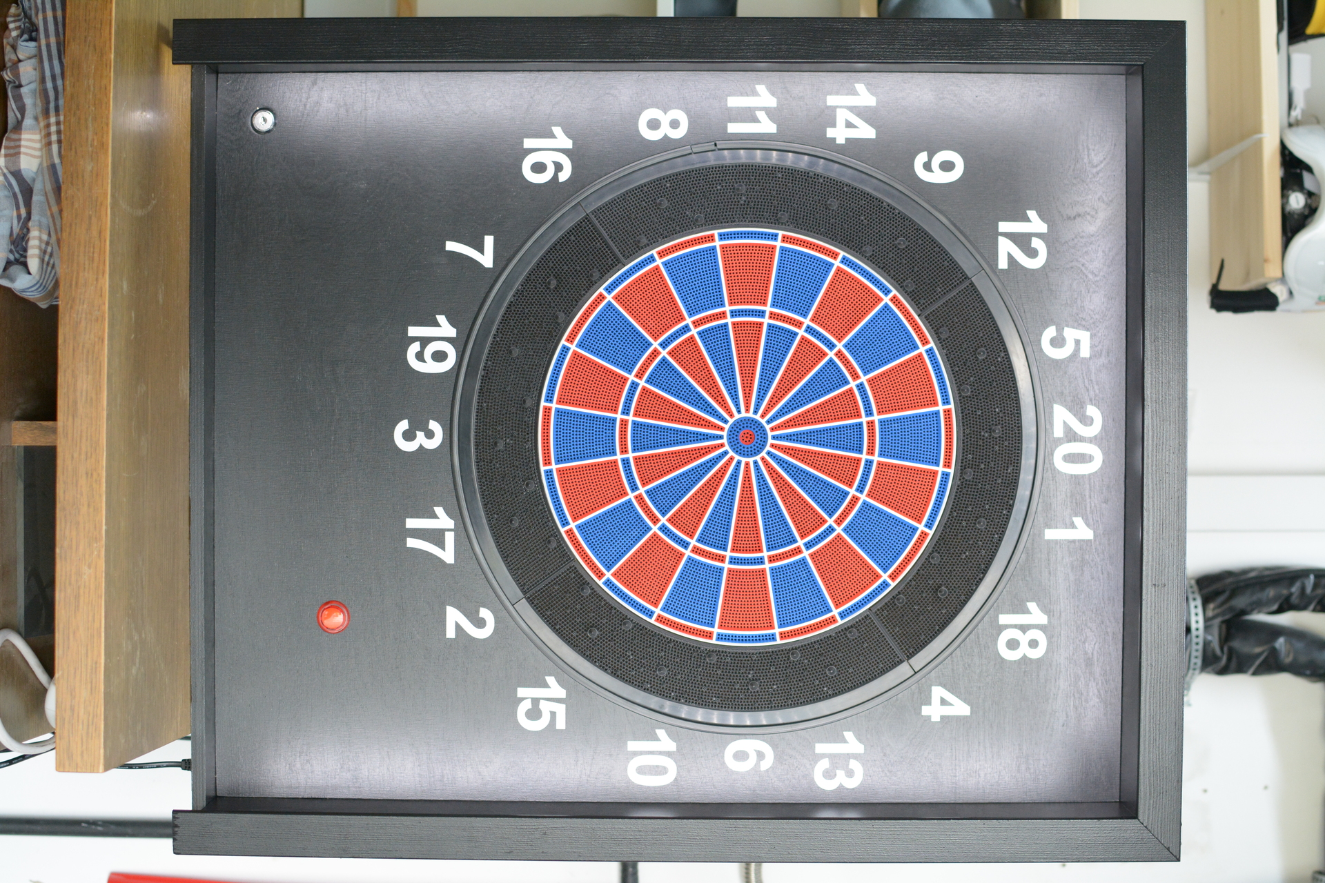
5.12 - Step 12 - Applying numbers
Stick the self adhesive numbers to the door
To be actually able to tell where you need to hit the board you will need numbers on the door. I ordered self sticking numbers for that purpose.
Warning
Check here and then if you keep the right order. As you might tell confusing the numbers is a bad thing to do here :D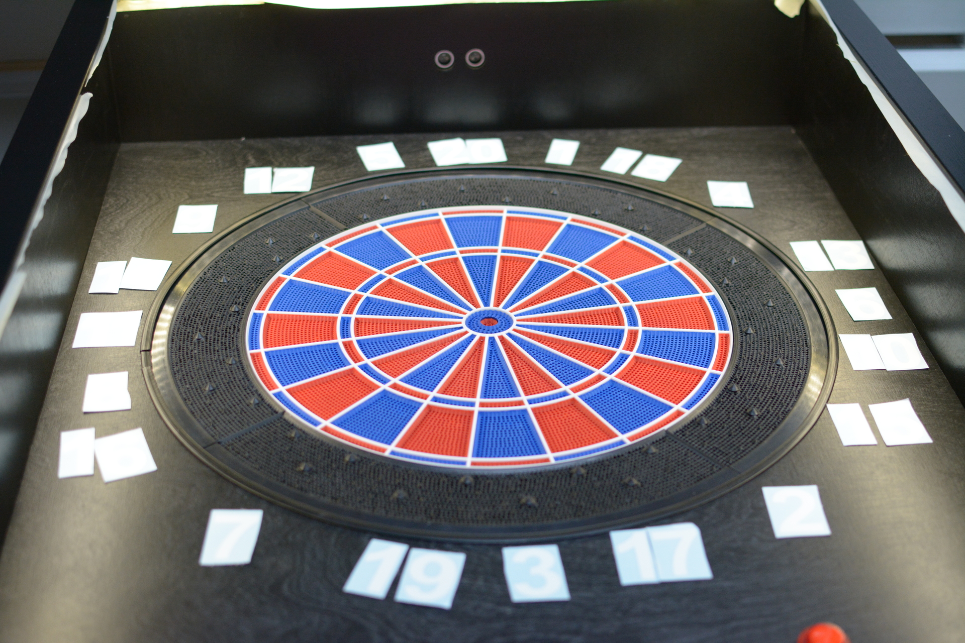
I used a template I made to find the middle of each segment. This helped me to align and stick the numbers to the right place.

Well, what should I say. Let there be patience and a sharp eye and eventually you are finished and your numbers now look like this.
This is how the machine will look like with numbers applied and LEDs turned on.
Next is the PCB (optional).
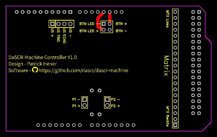
5.13 - Step 13 - Finish PCB
Solder connectors in place
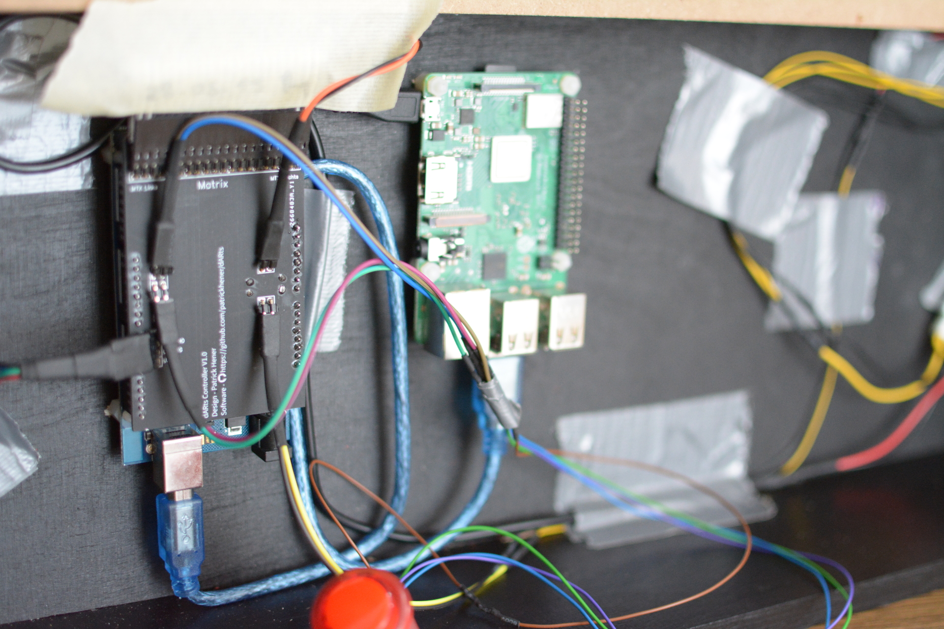
I designed this PCB to fit all my connectors comfortably and then connect in place onto the Arduino. This way you can quickly disconnect everything and reconnect it back again.
Info
This step is totally optional, as you could just connect the cables directly to the Arduino.
Also note that the pictures will show the old version and there is an updated version which will read the correct GitHub Repository.
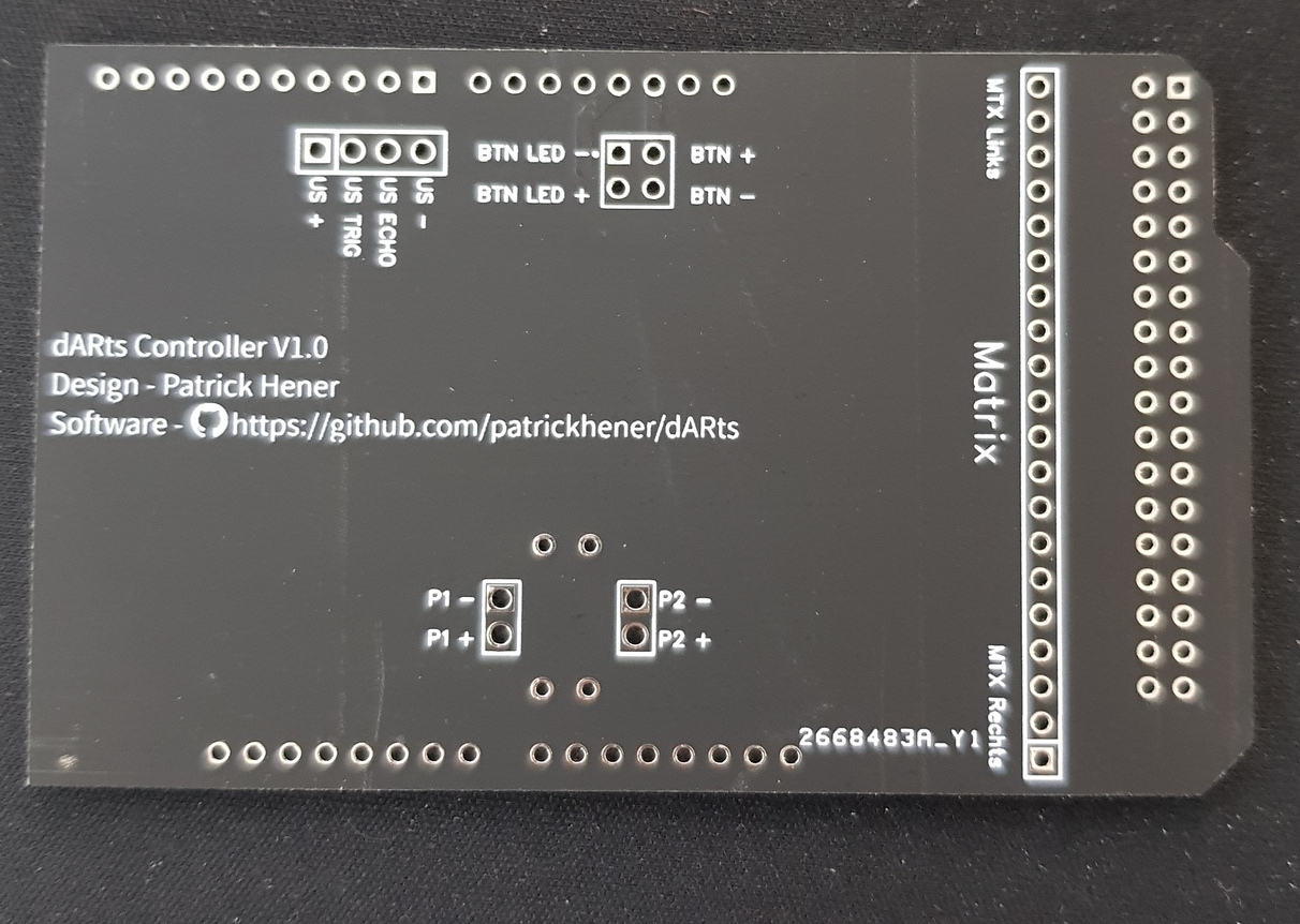
Now all you need to do is solder male sockets facing downwards onto the back side and solder angeled male sockets to the top side as pictured below.

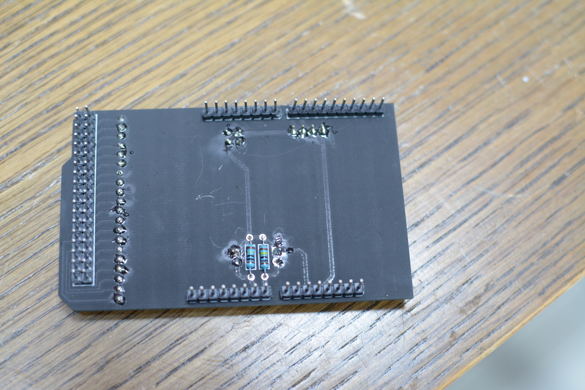
I applied the angled mail sockets in a really steep angle so the connects fit better later on.
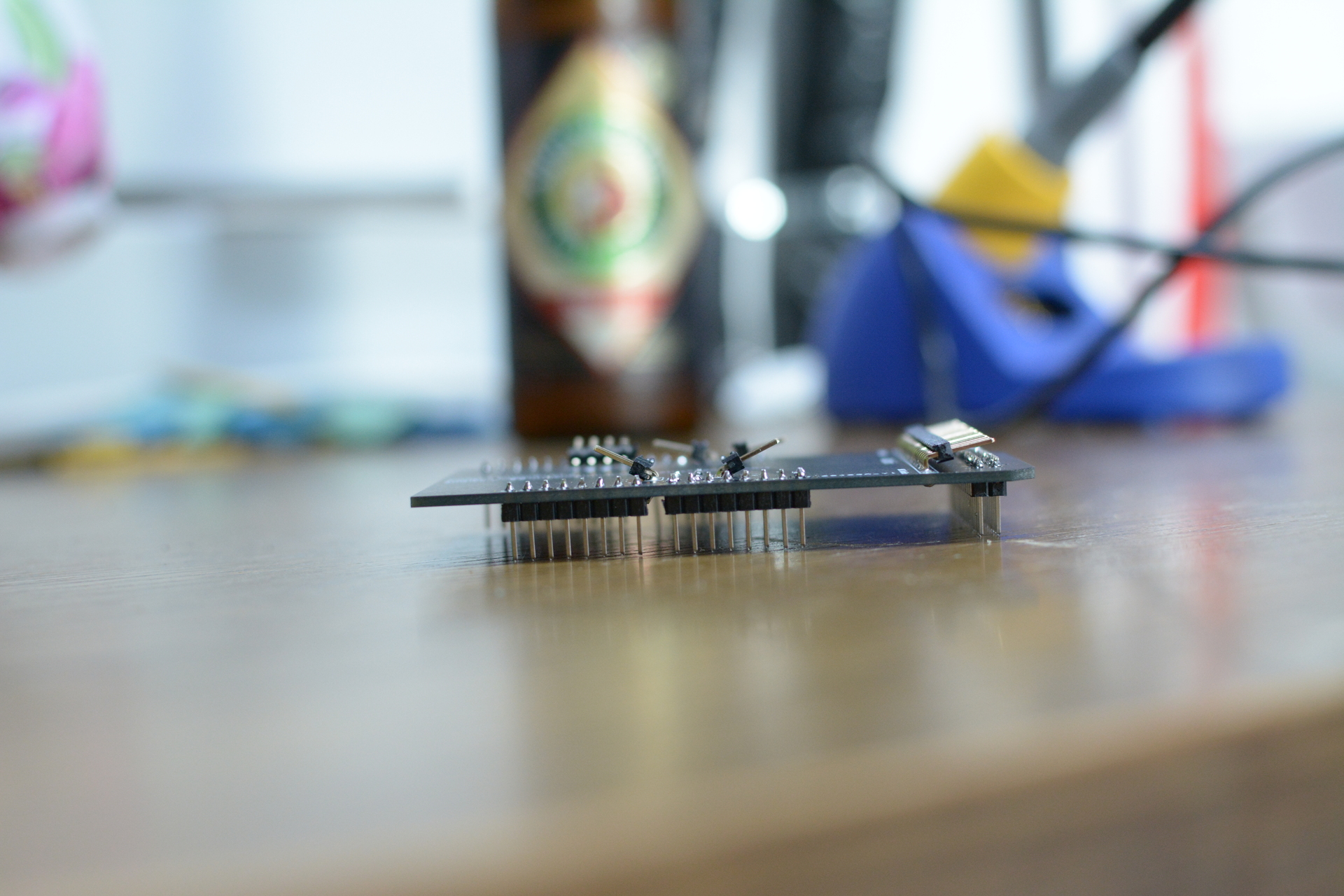
Now you can connect everything in place, which will look like so.
You are done now. This was the easy part (if you are more the woodworking guy) or the hard part (if you are more the software guy). Either way you can now continue with setting up OS, Software and such.
6 - Arduino
Flash the Arduino Mega 2560
For the inputs to handle we use an Arduino Mega 2560 which has a microcontroller. The controller is running a simple C++ program you can find in the GitHub Repository, readily available to be flashed.
You can either use Arduino IDE to do so. Just open the sketch, choose the right board type and port and then upload it to the Arduino.
Another possibility would be to use something like an Arduino-Makefile to transfer the ino sketch to a hex file and then flash it using avrdude.
For simplicity I suggest using Arduino IDE as it runs on all major Operating Systems.
7 - Raspberry Pi
Setup the Raspberry Pi
So I am using a Raspberry Pi 4 to connect the Arduino to. On the Raspberry Pi there runs a connector service which will handle the output of the Arduino and give it to the Scoreboard (in my case this is DaSCR-Board as you can tell).
For this purpose I am using go once again. You also can run DaSCR-Board and DaSCR-Machine all from that single Pi inside your darts machine. This should be enough ressources to handle both of it.
Prerequirements
Attention
As I am using the “embed” package of go introduced with go 1.16 you need to make sure you are using this version or a newer one.Also you system needs to have a running operating system (I chost raspbian for simplicity) and be integrated into a network. You can do that either using WIFI or a cable. Best would be to connect to the system via SSH for the next steps.
Installing Software
Clone or download the repository to that Raspberry Pi. In the folder called service you will find the go program.
Issue those commands to build it:
go mod download
go build -ldflags "-s -w" -o dist/dascr-machine
Now you will have an executable called dascr-machine in the folder called dist.
You can test run it from that folder calling the command from the listing below. Be sure to have the Arduino connected to the Pi.
INT=any ./dist/dascr-machine
You should see something like this when running:
❯ INT=any ./dist/dascr-machine
INFO   [2021-02-08 13:18:50] Navigate to http://0.0.0.0:3000 to configure your darts machine
INFO   [2021-02-08 13:18:51] Connected to websocket @ wss://demo.dascr.org/ws/dascr
....
Configure and autostart
You are almost already there. Now you just need to know how to configure it and how to autostart it when powering on the machine. That is pretty much simple.
First you need to understand that the webserver will be served on the IP address of whatever interface you provide with the environment variable INT. In the example above I chost it to be any which will just bind it to every interface. Most of the time this is the best option. You could have bound it to ethX or wifiX or whatever you Pi communicates with. I suggest you use any as I did.
Next up you can setup autostart using a systemd service file:
[Unit]
Description=DaSCR Machine
After=network.target

[Service]
Type=simple
User=patrick
Group=patrick
Restart=always
RestartSec=5s

Environment=INT=any

WorkingDirectory=/home/patrick/projects/dascr-machine/service/dist
ExecStart=/home/patrick/projects/dascr-machine/service/dist/dascr-machine
SyslogIdentifier=dascr-machine

[Install]
WantedBy=multi-user.target
Put the content of this listing into a file /etc/systemd/system/dascr-machine.service and then call:
sudo systemctl daemon-reload
sudo systemctl start dascr-machine
sudo systemctl enable dascr-machine
This will reload the systemd service and start the machine connector service. Also it will mark it to be autostarted when the machine powers on.
You can check the status of the service with this command:
sudo systemctl status dascr-machine
Final steps
Now you can navigate to the Raspberries IP address on port 3000 to setup the connection. When using any as interface it will tell you it’s 0.0.0.0 but it is not. You then will need to use the real IP address of your Pi like for example http://192.168.1.175:3000.
Navigate to it to configure your machine to use the Scoreboard and the Arduino.
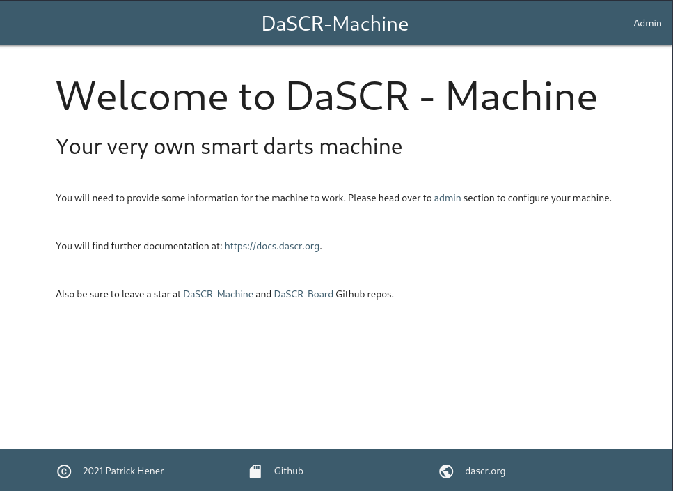
You will see the start page and click on the Admin link in the top left to see the setup dialog.
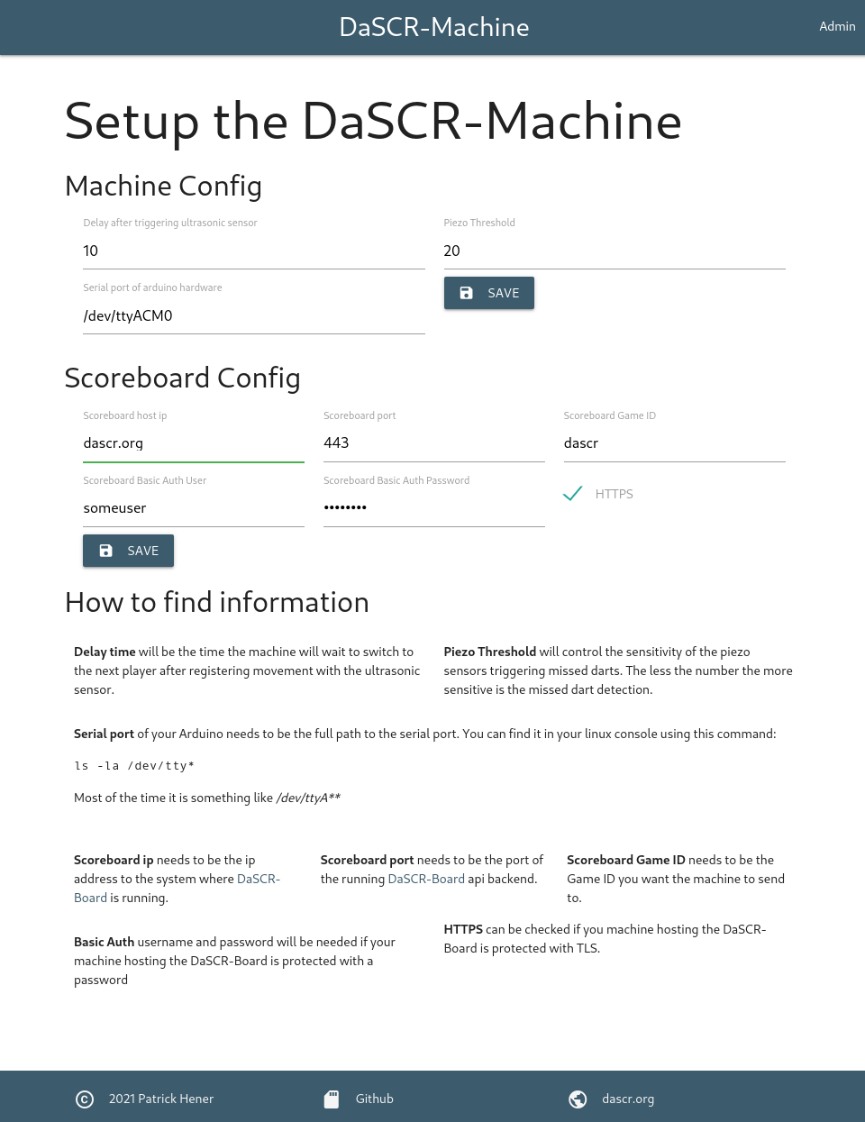
Be sure to fill in everything correctly:
-
Ultrasonic delay will tell the machine how long to wait until switching to next player after it was triggerd
-
Piezo threshold is a variable to controll the senitivity of the piezo sensors which will detect missed darts bouncing from the case or landing into the outer catch ring. 20 is a default which was working quite well for me. So my guess is you could just leave it there
-
Serial port needs to represent the connection of your Arduino. It will be listed in the directory
/devof your operating system and will almost certainly be of typettyAXXX. So runningls /dev/ttyA*in your PIs ssh session could tell you what to put here.
Hit ‘Save’ then to save the configuration.
Then proceed with scoreboard configuration
You need to fill in ip address and port of the system running the scoreboard. If you are running it on the same Raspberry Pi in the machine you can put localhost and port 8000 I suppose. Otherwise refer to the system with the public IP address and the API Port. You also need to choose the game id the machine should send the score to.
When running against a publicly available instance of DaSCR-Board like I did in the screenshot above you might need to put in Basic Auth credentials and choose wether to use HTTPS or not.
If you ran through the guide of DaSCR-Board and how to get it up and running you certainly know what to put here.
Shutdown button:
There is a shutdown button to stop the underlying Raspberry Pi. If you want to use that you might need to issue this to allowing your user to shutdown the Pi:
sudo chmod 4755 /sbin/shutdown
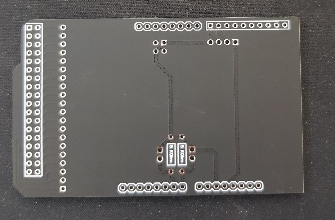
8 - Custom designed PCB
This is about the custom PCB I designed to fit the Arduino
Using EasyEDA I designed the header PCB to fit on top of the Arduino Mega 2560.
Using it is totally optional, although I recommend using it for easier connecting the cables to the Arduino.
You can find it in the repository as a gerber files bundle in zip format.
I ordered mine from here and it took about a few days and was kinda really cheap. Although I needed to order 5 pieces it was about 7,50 € including shipping to Germany.